Cooling systems in ultrafine graphite mills manage intense frictional/impact heat (99% of input energy lost as heat) by combining active heat removal (water jackets, chilled air, cryogenic gases) with passive design (thermal insulation, optimized flow paths) and precision control (PID loops, temperature sensors). They protect graphite’s crystalline structure, prevent oxidation/degradation, and ensure consistent particle size distribution for critical applications like lithium-ion battery anodes .
1. Heat Generation in Ultrafine Graphite Mills
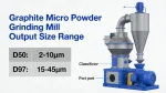
Ultrafine grinding (typically D97 < 10 μm) produces extreme temperatures due to:
- High energy density: Small grinding media (0.1–5 mm) with 10–50 m/s tip speeds create massive friction and impact forces
- Mechanical energy conversion: ~99% of input power converts to heat (only 1% for particle size reduction)
- Graphite properties: High thermal conductivity (150–190 W/m·K) transfers heat rapidly through the material and mill components
- Shear forces: Interparticle friction and particle-mill wall collisions generate localized hotspots
Critical consequences of overheating:
- Damage to graphite’s layered crystal structure, reducing conductivity and lubricity
- Oxidation (especially above 450°C in air), forming CO/CO₂ and degrading purity
- Agglomeration of fine particles, altering particle size distribution
- Thermal expansion of mill components, causing misalignment and increased wear
2. Primary Cooling System Types and Mechanisms
A. Water-Based Cooling Systems (Most Common)
| Component | Design | Working Principle | Cooling Capacity |
|---|---|---|---|
| Double-layer spiral water jackets | Coiled tubes around grinding chamber, classifier, and bearings | Coolant (typically 15–25°C) circulates through jackets, absorbing heat via conduction | Removes 60–80% of total heat; maintains chamber temp <80°C |
| Internal spray cooling | Nozzles directing fine water mist into grinding zone | Evaporative cooling + direct heat absorption; often uses deionized water for purity | Effective for localized hotspots; must control moisture (≤0.5% for dry grinding) |
| Closed-loop chiller systems | Integrated refrigeration unit with heat exchanger | Cools recirculated water to 5–15°C with precise temperature control (±0.2°C) | Enables stable operation even under variable loads; ideal for high-purity applications |
Key advantage: Water’s high specific heat capacity (4.18 kJ/kg·K) enables efficient heat removal with minimal flow rates
B. Air and Gas-Based Cooling Systems
| System | Configuration | Working Principle | Best Applications |
|---|---|---|---|
| Forced air cooling | External blowers + finned heat exchangers on mill housing | Ambient air (or pre-cooled to 0–10°C) flows over hot surfaces, carrying heat via convection | Supplementary cooling for low/medium heat loads; prevents condensation |
| Inert gas cooling | Closed-loop nitrogen/argon circulation with chiller | Inert gas acts as both cooling medium and oxygen barrier; cooled to -20 to +10°C | Prevents graphite oxidation; ideal for high-purity applications |
| Jet mill cold air injection | Pre-cooled compressed air (-10 to +5°C) introduced into grinding chamber | Adiabatic expansion cools air further (Joule-Thomson effect); carries heat with exhaust | Primary cooling for fluidized bed jet mills; maintains <50°C in grinding zone |
C. Cryogenic and Advanced Cooling Methods
-
Liquid nitrogen cooling: LN₂ injected into mill chamber, vaporizing at -196°C to absorb massive heat (199 kJ/kg latent heat)
- Creates sub-zero grinding environments (typically -20 to -80°C)
- Preserves graphite’s crystal structure and prevents thermal degradation
- Used for high-value applications (battery materials) where particle integrity is critical
-
Hybrid systems: Combine water jackets (for mill structure) with cryogenic gas (for grinding zone) for comprehensive temperature control
3. Component-Specific Cooling Implementation
Grinding Chamber Cooling
- Double-walled construction: Outer jacket with spiral channels for coolant flow maximizes surface contact
- Internal cooling inserts: Heat-conductive metal plates (stainless steel, aluminum) with embedded cooling channels placed near high-friction areas
- Jacketed classifier housing: Controls temperature in the critical particle separation zone to prevent agglomeration
Grinding Media and Rotor Cooling
- Hollow grinding media: Coolant flows through internal channels of balls/rods to remove heat from the core of grinding action
- Cooled agitator shafts: Liquid-cooled shafts for stirred mills (attritors) remove heat directly from the high-speed rotor
- Air-cooled classifier wheels: Prevents thermal expansion that could alter precision particle size classification
Auxiliary Component Cooling
- Bearing cooling: Water-cooled bearing housings maintain lubricant viscosity and prevent premature failure
- Motor cooling: Liquid-cooled stators for high-power (50–500 kW) mill motors operating at 90–98% efficiency
- Dust collection cooling: Prevents filter media degradation from hot exhaust gases (up to 150°C)
4. Cooling System Operation and Control
Step 1: Heat Detection
- Multiple temperature sensors: PT100/RTD probes at grinding chamber walls, bearing housings, and exhaust gas outlets
- Infrared thermography: Monitors external mill surface for hotspots
- Differential pressure monitoring: Tracks cooling system efficiency (clogged filters increase pressure drop)
Step 2: Heat Removal Process
- Heat transfer: Generated heat moves from graphite particles → grinding media → mill walls → cooling medium (water/air) via conduction/convection
- Coolant circulation: Pumps/chillers maintain constant flow rates (typically 5–20 L/min per kW of mill power)
- Heat dissipation: Coolant releases heat via:
- Air-cooled heat exchangers (for water systems)
- Chiller refrigeration cycles (for closed-loop systems)
- Direct exhaust (for gas cooling systems)
Step 3: Precision Temperature Control
- PID control loops: Adjust coolant flow/temperature based on real-time sensor data, maintaining ±1–2°C stability
- Automatic shutdown: Mill stops if temperatures exceed critical thresholds (typically >120°C for graphite)
- Variable speed drives: Modulate mill RPM to balance throughput and heat generation during peak loads
5. Graphite-Specific Cooling Challenges and Solutions
| Challenge | Solution |
|---|---|
| Oxidation sensitivity (starts at ~450°C in air) | Inert gas (N₂/Ar) cooling systems with O₂ monitoring (<5% O₂) |
| Moisture contamination risk (affects battery performance) | Dry cooling methods + dehumidification; water systems with zero-leak design |
| Thermal conductivity (rapid heat spread) | Multi-zone cooling with localized temperature control |
| Particle agglomeration at high temperatures | Sub-ambient cooling (<25°C) to reduce van der Waals forces |
| Crystal structure preservation | Cryogenic grinding for critical applications (battery anodes) |
6. System Design Best Practices
- Cooling capacity matching: Design for 120–150% of maximum heat load to handle process variations
- Redundant systems: Dual cooling loops prevent catastrophic failure during maintenance
- Heat recovery: Capture waste heat for facility heating (improves energy efficiency by 15–25%)
- Material selection: Use corrosion-resistant materials (stainless steel, titanium) for cooling jackets to avoid contamination
- Insulation: Thermal barriers between hot grinding zones and sensitive components reduce heat migration
7. Typical Temperature Ranges for Effective Operation
- Grinding chamber: 25–80°C (dry grinding); 10–40°C (wet grinding)
- Classifiers: <60°C to prevent particle agglomeration
- Bearings: <70°C for optimal lubrication performance
- Critical applications (battery materials): <40°C to maintain graphite’s electrochemical properties
Cooling systems in ultrafine graphite mills act as the “thermal backbone” of the process, combining multi-stage heat removal, precision control, and graphite-specific engineering to prevent overheating. By managing temperature throughout the grinding circuit, these systems ensure consistent product quality, protect equipment longevity, and enable production of high-performance graphite powders essential for advanced technologies .
For optimal results, cooling systems should be custom-designed based on mill type (ball, stirred, jet), throughput, desired particle size, and end-use application requirements.