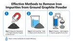
The most effective iron removal from ground graphite powder typically uses a multi-stage approach combining magnetic separation (for ferromagnetic particles) and chemical leaching (for oxidized and chemically bound iron), followed by thermal treatment for ultra-high purity applications. The optimal process depends on iron form (free iron, oxides, silicates), required purity level (industrial vs. battery-grade), and production scale.
1. Iron Impurity Forms in Graphite Powder
| Iron Type | Magnetic Property | Removal Difficulty | Common Sources |
|---|---|---|---|
| Free iron (Fe⁰) | Strongly magnetic | Low | Grinding equipment wear, contamination during processing |
| Iron oxides (Fe₂O₃, Fe₃O₄) | Weakly to moderately magnetic | Medium | Mineral impurities, oxidation of free iron |
| Iron silicates (e.g., fayalite) | Non-magnetic | High | Primary mineral in graphite ore, difficult to dissolve |
| Iron carbides (Fe₃C) | Weakly magnetic | Medium-High | Graphitization process byproduct |
2. Core Removal Technologies
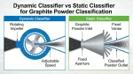
A. Magnetic Separation (Primary Stage)
Most cost-effective first step for removing magnetic iron fractions (free iron, magnetite).
-
Dry High-Intensity Magnetic Separation (DHIMS)
- Best for: Dry ground graphite powder (particle size 10–500 μm)
- Equipment: Rotating drum separators, electromagnetic separators with NdFeB magnets
- Key parameters:
- Field strength: 12,000–15,000 Gauss for strong magnetic iron; 20,000+ Gauss for weak magnetic oxides
- Feed rate: Thin layer (≤5 mm) for optimal separation
- Multiple passes (2–3 stages) to achieve 90–95% removal of magnetic iron
-
Wet High-Gradient Magnetic Separation (WHGMS)
- Best for: Fine graphite powder (<10 μm), especially for lithium battery applications
- Advantages: Prevents dust, better particle dispersion, higher recovery of fine iron particles
- Materials: Use 316L stainless steel or PTFE coatings to avoid secondary contamination
-
Gradient Magnetic Separation
- Advanced technique: Matches magnetic field strength to particle size (coarse = lower field; fine = higher field)
- Achieves up to 98% removal of magnetic iron impurities
B. Chemical Leaching (Secondary Stage)
Removes non-magnetic iron oxides and chemically bound iron after magnetic separation.
-
Hydrochloric Acid (HCl) Leaching (Most Common)
- Reaction: Fe₂O₃+6HCl → 2FeCl₃+3H₂O; Fe₃O₄+8HCl → 2FeCl₃+FeCl₂+4H₂O
- Optimal conditions:
- Concentration: 6–8 mol/L (30–37% HCl)
- Temperature: 70–80°C (343–353 K)
- Solid-liquid ratio: 1:10 (0.1 g/mL)
- Time: 60–120 minutes with 400 rpm stirring
- Removal efficiency: 90–95% for iron oxides
-
Sulfuric Acid (H₂SO₄) Leaching
- Better for: Iron silicates and refractory iron compounds
- Conditions: 2.5–4 mol/L, 90–150°C, 4–6 hours
- Caution: May leave sulfate residues; requires thorough washing
-
Alkali-Acid Combination (NaOH-HCl)
- Process:
- Alkali fusion: Mix graphite with NaOH (3:1 ratio), roast at 600°C for 2 hours to break down silicates
- Acid leaching: Treat with 1–2 mol/L HCl at 60°C for 40–60 minutes
- Removes both iron and silicon impurities simultaneously
- Iron removal: 95–98% for combined iron-silicate impurities
- Process:
-
Chelation-Assisted Leaching (Advanced)
- For: Residual iron after standard acid treatment
- Use: EDTA or citric acid at pH 8–9 to chelate remaining iron ions
- Effective for: Battery-grade graphite requiring <10 ppm iron
C. Thermal Purification (Tertiary Stage)
For ultra-high purity graphite (battery, semiconductor applications) requiring <5 ppm iron.
-
High-Temperature Graphitization
- Process: Heat to 2800–3000°C in inert atmosphere (Ar, He)
- Mechanism: Iron impurities vaporize and diffuse to graphite surface, then removed by gas flow
- Effectiveness: Reduces iron to <15 ppm from natural graphite
- Cost: High energy consumption; suitable only for high-value applications
-
Halogenation Roasting
- Process: Treat with Cl₂ or I₂ gas at 900°C with H₂ addition
- Reaction: 2Fe + 3Cl₂ → 2FeCl₃ (volatile, removed by gas stream)
- Advantages: Removes both iron and other metallic impurities (Ca, Mg)
- Safety: Requires strict handling of toxic halogen gases
3. Recommended Multi-Stage Process Flow
-
Pre-treatment:
- Dry screening to remove large iron particles (>500 μm)
- Air classification to separate graphite from heavy mineral impurities
-
Primary Iron Removal:
- Dry high-intensity magnetic separation (12,000–15,000 Gauss) for 2–3 passes
- Removes 70–90% of free iron and strongly magnetic oxides
-
Secondary Iron Removal:
- HCl leaching (6 mol/L, 70°C, 90 minutes, 1:10 S/L ratio)
- Follow with water washing to pH 6–7 (critical to prevent chloride residues)
- Removes additional 80–90% of remaining iron oxides
-
Tertiary Purification (for battery-grade graphite):
- Wet high-gradient magnetic separation (20,000+ Gauss) to capture fine iron particles released during leaching
- Optional: Chelation treatment (EDTA, pH 8.5) for final iron reduction to <10 ppm
-
Post-treatment:
- Thermal drying at 120°C to remove moisture
- Purge with inert gas to prevent re-oxidation
4. Best Practices for Maximum Iron Removal
-
Match method to iron form:
- Use magnetic separation first for ferromagnetic iron (Fe⁰, Fe₃O₄)
- Use acid leaching for oxidized iron (Fe₂O₃) and iron hydroxides
- Use alkali-acid combination for iron silicates and refractory iron compounds
-
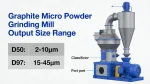
Optimize particle size:
- Grind to 90% < 45 μm for efficient magnetic separation and leaching
- Avoid over-grinding to prevent graphite flake damage and increased iron contamination
-
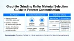
Prevent secondary contamination:
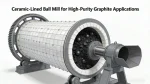
- Use ceramic or polymer-lined equipment during processing
- Clean all equipment thoroughly between batches
- Store purified graphite in airtight containers to avoid recontamination
-
Monitor iron content:
- Use ICP-MS for accurate measurement of iron concentration (ppm level)
- Test after each processing stage to adjust parameters accordingly
5. Application-Specific Recommendations
| Application | Required Iron Level | Recommended Process | Cost-Effectiveness |
|---|---|---|---|
| Industrial graphite | <500 ppm | Magnetic separation (2 stages) | High |
| Lithium-ion battery anode | <10 ppm | Magnetic separation + HCl leaching + WHGMS | Medium |
| Semiconductor-grade graphite | <5 ppm | Full process + high-temperature graphitization | Low |
| Recycled battery graphite | <20 ppm | Gradient magnetic separation + acid leaching + thermal treatment | Medium-High |
6. Environmental & Safety Considerations
- Acid waste management: Neutralize spent acid with lime/NaOH before disposal
- Magnetic separation: No chemical waste; iron contaminants can be recycled
- Thermal processes: Use energy-efficient furnaces; capture and treat off-gases
- Personal protection: Use acid-resistant gloves, goggles, and ventilation for chemical leaching
For most industrial applications, a two-stage process of magnetic separation followed by HCl leaching achieves 95–98% iron removal at reasonable cost, while meeting typical purity requirements (≤100 ppm iron). For battery-grade graphite, adding wet high-gradient magnetic separation and chelation treatment ensures iron levels below 10 ppm, critical for electrochemical performance.